Photo 1.1 |
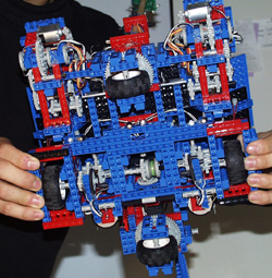
Photo 1.2 |
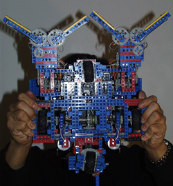
There are three main parts to the whole design of the robot. The first is the drive train and the platform for mobility. The second are the arms and their corresponding claws. The third is the retractable tail.
Platform and drive train
|
Photo 1.1 |
Photo 1.2 |
We choose a fairly unconventional platform. It is diamond shape
with two servors controlling the two wheels at the front and the back.
(See photo 1.1) The two side wheels are driven with two motors
each with a gear ratio of 27:1. The positive aspects of the design
is that we are very symmetric and stable, and is able to turn at any angle
on a clear axis through the center of the robot by turning the servor wheels
to 90 degrees and powering the drive wheels in the opposite direction.
(See photo 1.2) The negative side of the design is that we
use one more servor for turning than most people. The original rationale
behind pursuing this design is because we are planning to have a tail as
well as arms, so it is important to remain stable around a center point.
Also we plan to do line-following, thus the ability to turn through a axis
in the center of the robot is a plus. The wheel of the robot is stuffed
with paper and rubber band to minimize deformation of shape when pressured
with the weight of the robot. This method works well to keep the contact
point of the wheels small enough so we could turn the servors with a good
degree of accuracy.
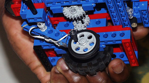
Photo 1.3 |
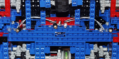
Photo 1.4 |
Shaft Encoders and light sensors are utilized in our platform and drive train design. Two free shaft encoders are built at the underside of the robot close to the two driving wheels. These shaft encoders are kept sticking to the ground by pressure from rubber bands. (See photo 1.3) Three light sensor are also built as close to the drive wheel as possible with one in the center and two to either side, at approximately 2.5 inches away from the center. (See photo 1.4) The rationale behind three color sensor is that we need minimum three to implement line following. There is also an additional benefit by placing them as close to the center as possible: we might be able to turn 90 degrees using them at places where we find black line crossing.
Arms and claws of the Scorpio'bot
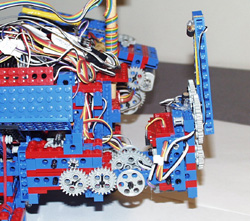
Photo 1.5 |
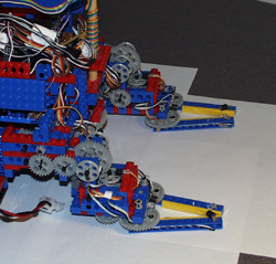
Photo 1.6 |
The most complicated part of our robot design are the arms and claws. A total of four motors, four shafter encoders, and four light sensing pairs to are used to implement the arms and the claw. The arms are able to accurately lift up and down independently using two separate motors. (See photo 1.5 and 1.6)
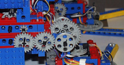
Photo 1.7
The angle at which it lifts is controlled by two shaft encoders placed
on the third gear from the motor. (See photo 1.7) A high ratio
but compact gear box using a worm gear is designed for the claws to limit
the size and weight. Two more shaft encoders are used to on the pair
of claws to sensor the closing and opening of the claws. (See
photo 1.7)
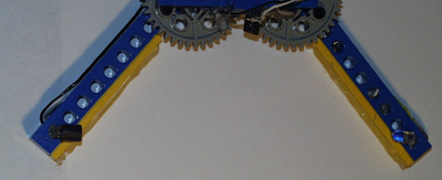
Photo 1.8 |
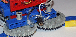
Photo 1.9 |
When the claws open, a pair of light emitting diode and light receiving
transistor is located at the tip of the claw facing each other. (See
photo 1.8) When the open claw is lowered flat against the floor
of the table, any object passing into the claw is sensed by these light/receiver
pair. The next step is to close the claws. When the claws close
around the object, which we hope is a student or hacker block, a pair of
light emitter and receiver at the base of the claw "looks" forward to give
a reading of the color of the block. (See photo 1.9) Given
a black block, the arm would raise and drop the block into the bin on the
back of the robot. If the block was white, the claw would open, the
arm would raise, and the robot would drive forward for a little before
lowering the arm again to sense more blocks.
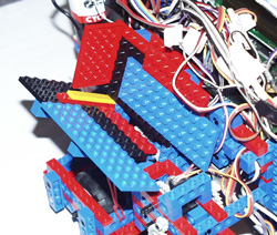
Photo 1.10 |
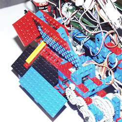
Photo 1.11 |
The hackers blocks are placed into two separate bin on top of the robot. The two bins are controlled by a single servo. When all the blocks are collected, or when the time is close to finish, the robot is to drive to the jail, position itself along the side of it and open one bin, spin 180 degrees, and open the other bin. This way we can dump all the hacker blocks into the jail at the end of the game. For operation of the bins, please refer to photo 1.10 and 1.11.
The tail of Scorpio'bot
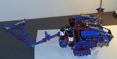
Photo 1.12 |
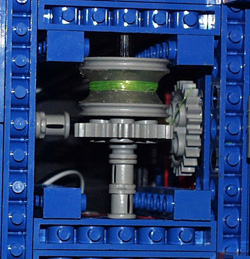
Photo 1.13 |
The tail of the robot is a simple release design controlled by a motor and fishing lines. When the motor turns and releases the fishing line, the tail "strikes" out. The motor is then able to run in the opposite direction and thus wind up the line and pull the tail in. The gears that powers this mechanism is hidden deep within the "belly" of the robot. (See photo 1.12, 1.13, 1.14)
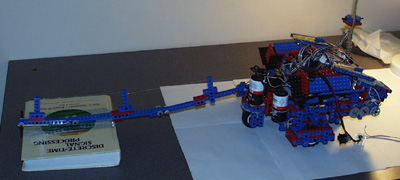
Photo 1.14