Actuators, Structural Design, and Overall Mechanics
General Comments
The mechanics of our robot were our failing. Our robot was too top
heavy, causing it to be unbalanced. When driving straight, our robot
would kind of waddle. If we had a mechanical engineer on our team, he
would have probably recognized this flaw in our design quickly. Alas,
we didn't realize the flaw until too late (or too lazy to rebuild
anything).
Geartrain
We were so proud of our geartrain after we had built it. We stopped
with our 8th iteration. It was compact and fast. We used a 27:1 gear
ratio. Each geartrain had three motors for maximum power. In addition
we used the smaller 2.5 inch black tires. Too bad our robot lost all
speed after we loaded the robot with more parts, the Handyboard, and
batteries. In retrospect, we should have used a higher gear ratio and
larger tires. However, the bracing around our gearbox was
unbelieveably strong.
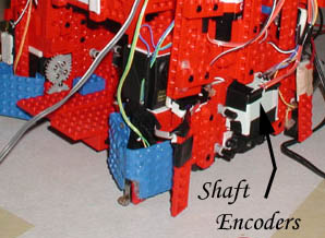
Shaft Encoders
These things were both good and bad. We had them mounted on the axle
just under the motors, which meant they were spinning at 1/3 the speed
of the motors. This placement gave us good resolution, but the high
resolution was quite unnecessary. By the time our motors reached the
desired number of ticks, it still took another 10-50 ticks to stop the
robot depending on how fast our robot was initially moving. We felt
the shaft encoders were good for getting the robot into the general
vicinity of going straight, turning, and going where you wanted to
go. However we would not recommend using them for anything too
accurate. Use wall following or aligning with the wall for much more
accurate movements. One last thing we did was shield the shaft
encoders in a cardboard box. The lighting in 26-100 was very strong
and could easily throw off the readings if they were exposed.
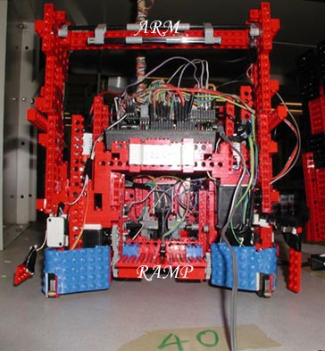
Ramp to lift up ball
Another part of our robot was a ramp device that could lift up a ball.
When the ramp was down, we could jam a ball between the ramp and a
wall. Then we would raise the ramp causing the ball to roll into the
body of our robot. To power the ramp, we used a servo. We screwd a
24-tooth gear directly onto the servo. Then we used that gear to power
another 24-tooth gear that was connected to the ramp. Not having the
servo directly connected to the ramp gave use a few problems. Mainly
there was a great deal of play between the two gears and if there was
too much stress on the ramp, the gears would just give. We would hear
these painful clicking noises as the teeth just slide past each other.
Overall, though, the ramp worked fine. Under most conditions it lifted
the ball. Occasionally it lifted the ball too well and would flip the
ball over the wall. We placed a small bump sensor on the ramp to
detect the presence of a ball. In our strategy we could use this
sensor to tell us whether or not the robot should make another attempt
at picking up the ball. Oh yah, the ramp could be used as a faux
switch, which made our robot bounce like the ghetto pimp ride it is.
Arm collection system
We built a very cool arm. It was sturdy as heck. During practice runs
we would have our robot bang its arms down on the table. It made a
loud 'thud' noise. In addition to being sturdy, the arms had a gate in
the front. The gate allowed balls to come into the arms, but not out.
We initially planned to use this design for plowing over balls and
containing them. By contest time, this feature was completely ignored
and we concentrated on using the sturdiness of our arms to bash
things.
The arm was connected to a servo on one side and a free spinning grey
connection thing on the other. Having the arm powered on one side made
it a little unbalanced, but it worked. The arms lifted and lowered
very reliably.
Back to the Main Page