6.270 Autonomous Robotics Competition: Chicken (2002)

|
Team 50 -- Colonel Sanders Claudio Brasca, Xian Ke, Adrian Solis (view photo) |
Strategy
• Structure • Drive System
• Electronics • Code
• Final Thoughts
|
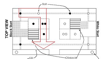
Our main strategy was to pick up and store on our robot as many balls as we can from our side of the table, then eject them into a chute. By opening one of two exit gates, we can place our opponent's ball inside the chute before our own. In this way, our score is maximized. We start by orienting ourselves so that the back of our robot is facing the chute. We drive straight backwards to knock over the first ball. This would make sure that we score one point as fast as possible. We then drive straight forward toward the opposing wall. Using distance sensors on our right side, we can at this time determine the position of the block. The block position determines our path for the remainder of the 60-second game period. The picture below illustrates our expected path for one block position.
After picking up all the balls along our path in this manner, we determine the location of the other robot. If the robot is not on our side of the table, we attempt to dump all our balls into our chute, with the opponent's ball dumped first. Otherwise, we dump the balls into the opponent's chute. |
|
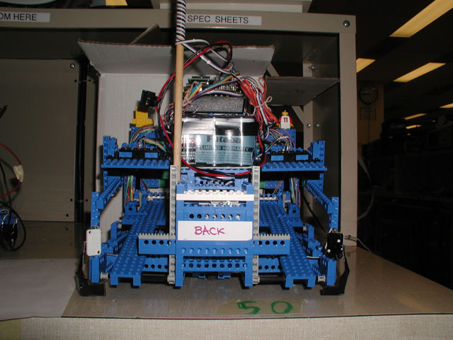
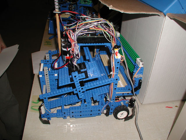
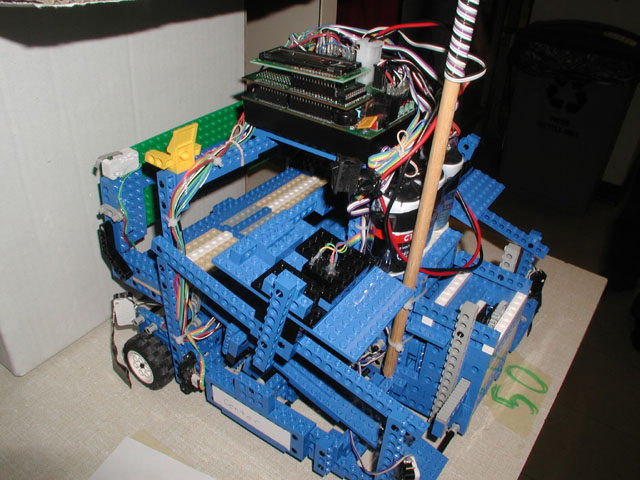
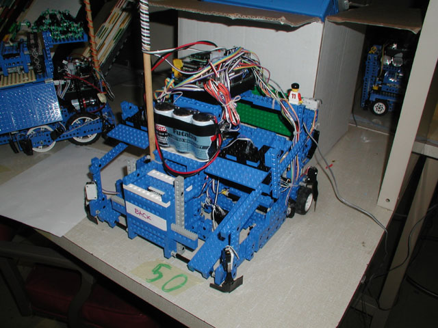
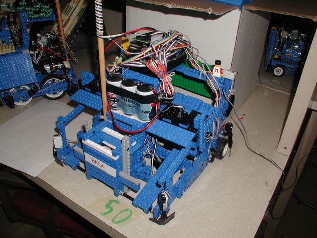
Structure The structure of our robot is fairly complicated and at the end of the third week of IAP we had used almost every single part of our Lego kit. The robot is built around a light but rigid frame which is approximately 1 ft by 1 ft, and 2.5 inches high. Integral parts of the structure are the two front wheels, the back steering wheel/servo, and the six motors and associated gears (more about this in the Drive System section). Attached above the two front wheels is a plow capable of lifting two balls at the same time. The plow is built with the help of the base plate and is operated by two motors connected through a ~900 gear ratio to the plow. This is probably the most remarkable capability of our robot. On the back, two doors (operated with the help of a servo) allow the release of balls from the selected side. This was supposed to allow us to use the opponent's balls to increase our score. The handyboard and the battery back (3) were placed on a light overstructure which was connected to the frame with vertical beams placed on the sides of the robot and above the steering servo. |
 |
The drive system was definitely the most poorly designed feature of
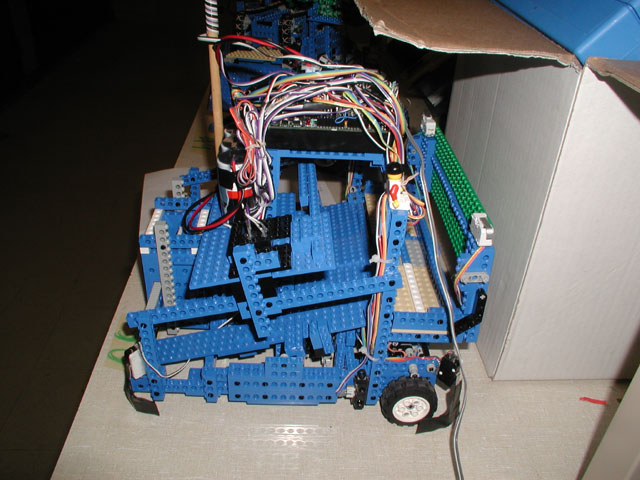
the robot. This problem was addressed in our second design when we actually replaced the two back wheels with a sigle steered undriven wheel at the center of the structure. This added some maneuverability to the system. With a gear ratio of 45 for the driving wheels and engines placed longitudinally to the main axis of the robot, we were forced to use slanted gears which proved very unreliable. This for instance caused us to loose our game in the second round, when one of such gears came loose and started grinding. An additional problem with this design was that we could only turn around a pivot point placed somewhere in the front of the robot. With a frame already so big this meant we could turn in place only with the help of repeated manuvers. |
|
To perform its strategy, our robot had to have quite a few sensors. But first things first -- we had to qualify for the contest. To do this, we had to be able to (1) detect the orientation of the robot, and (2) detect the starting light flashing underneath the robot. All together, this required 4 color sensors, which were basically CdS cells (photoresistors) responding to changes in the reflectivity of the underlying surface. Illumination was provided by a bright red LED. The color sensors were arranged in a "broken square" pattern : 3 of the sensors were placed at the corners of a square, with the last one placed at the center. The three outer sensors allowed us to determine both our color and orientation; the center one was used to detect the start signal, with talk of using it later on for 3-sensor line following. To detect the color of the balls in the storage areas, we installed 2 color sensor in canopies looking down on the storage areas. These sensors has consistently high readings due to the relatively dark conditions of the chute, but would plummet when a ball passed under them, as the balls were relatively reflective. We wrote code to detect this condition, and based our color decisions on the minimum value the sensors acheived. Although this functionality was never used during the contest, testing showed it to be quite reliable. We put two distance sensors on our robot, one on each side. We wanted to use them to detect the placement of the block, and since our strategy called for the robot to move toward the chute no matter what its starting position was, we needed distance sensors on both sides. However, we never really figured out how to figure out the position of the block in a foolproof manner. It didn't help that the distance sensors were REALLY flaky! Ugh, these bad boys were definitely overhyped. We weren't that successful in using them for wall-following either, because they conked out when the wall was closer then three inches. With a robot our size, you're always closer than three inches! Also, they tended to detect random things like the floor (so you couldn't put them too close to the ground) or the robot itself (precluding a more internal placement). We also installed an electric eye in the front portion of the scoop to alert us to the presence of a ball there. Because we were having difficulty picking up the balls, we thought it would help to if we charged ahead at full speed until the ball was on the scoop, then raised the scoop to bring the ball up. To do this, we installed an infrared LED on one side of the scoop and an infrared phototransistor on the other side. The idea was to have a beam from the LED to the transistor across the scoop, which would then be blocked by a ball on the scoop. This worked fairly decently. |
|
Our code, which started out simple, grew increasing complex as we attempted to deal with the mechanical deficiencies faced by our robot. We implemented software for many functionalities which we did not end up utilizing during the course of the contest. These include plow "electric eye" detection of balls entering the plow, color detections of balls as they are being stored, and block detection using distance sensors. A large percentage of our code were test code used to make sure that numerous features such as line following, wall following, and turning worked correctly. Unfortunately, perfect functionality largely proved elusive. We encountered the limits of Handyboard memory at several occasions, forcing us to trim the code. Since our robot was unable to turn in place, we attempted to emulate this in software by making the robot go straight backwards as it turned. This prevented the robot from getting stuck at the initial position trying to orient itself, but was far from perfect due to unreliable shaft encoder readings to determine the turn angle. For a while, we experimented with using modulation to achieve speeds between the 7 or 8 the Handyboard provided. Unfortunately, this was not very successful, as modulation produced visible irregularities in the motion. This was especially obvious at low speeds, when the "modulation" consisted of stopping and starting the engine. |