Team 42: Hindenbot
Specs
|
Power: 6V Hawker lead acid batteries
Driving:
Differential rear wheel drive on two back wheels
Steered by single servoized caster in front
Employed shaft encoding and gyro as feedback for steering
15:1 gear ratio on wheels
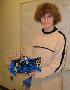
Dimensions:
1 foot x 1 foot
Sensors:
8 bump sensors,
6 IR sensors,
2 shaft encoders,
1 Gyro
Blown/broken electronics:
7 motor chips,
5 servos,
2 bump sensors,
1 gyro,
1 handyboard
|
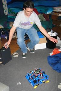
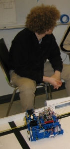
The Team
The Timeline
Assignment 2
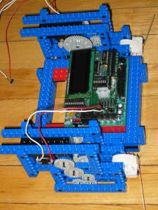
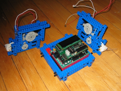
We utilized two 45:1 gear trains to differentially drive a robot forwards, backwards, clockwise, and anticlockwise.
The gear trains, motors, and wheels were all housed in two separate modules that attached to either side of a center mounting for our handyboard.
We also mounted a bump sensor on the front of this robot. When depressed, the sensor would make the robot back up and turn around.
Finally, after the robot went through its specified sequence of actions, it was programmed to play Nazareth's "Hair of the Dog."
Assignment 3
For Assignment 3, we used the same robot as in Assignment 2, but modified its code. Instead of simply going forwards, backwards, and turning, the robot oriented itself towards an arbitrarily positioned target and drove towards it until it was within a specified tolerance.
The code that we wrote for this assignment calculated our robot's direction of travel, and compared it to a vector from our robot to the target using RF data. The robot would turn and reorient itself until the difference between the angles of the two vectors fell within tolerance, and then would drive forward again. Because this assignment showed us that RF data was imprecise and only slowly sampled, we decided that in our next robots, our code should not rely so heavily on RF positioning.
Assignment 4
Assignment 4 asked us to briefly describe our intended strategy. Our writeup called for a robot with a sorting mechanism, two separate corrals, and a "Ballzooka" for a voting mechanism.
We proposed using a differential drive system with shaft encoding and a gyro to allow the robot to steer and maneuver.
Assignment 5
Assignment 5 wanted us to build a beta version of our contest robot which would be capable of orienting itself given an arbitray starting direction.
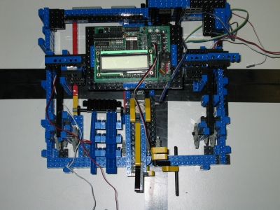
Our beta bot was a large, square, 1 foot x 1 foot behemoth with two separate corrals. We abandoned the idea of a "Ballzooka" and a sorting mechanism because both devices were difficult to design and did not mesh with the other elements of our robot.
However, we did add on a feature: we incorporated a "Balljector" (a scissor jack for voting) that we extended and retracted using a servo.
In addition to the balljector, our robot had two wheels that were each driven by separate motors (each employed a gear ratio of 45:1).
Because our gyro was malfunctioning, we were not able to use it for steering. Therefore, the only sensor on the robot was an IR sensor for initial orientation. As time went on, we also attached two gate mechanisms controlled by servos which were intended to allow balls in and keep balls in for their open and closed positions respectively.
Cheesy hypnotic animated gifs:
Revision 2
Thinking our beta bot was not a particularly competitive design, we dismantled it completely and began again. Our hope was to build a robot that would drive over balls, lift them to a sorting area, and then corral balls into seperate "Ballsevoirs."
We built several components for this robot, including a "Ball-evator" (a series of out of phase hands that lifted the ball by passing it to a higher layer of hands). We also built a ballsevoir.
However, the ballsevoir could not reliably vote, initially getting the balls to the first pair of ball-evator hands proved too serious problems to ignore. We therefore decided to modify the original design of our beta bot, and begin coding in strategies for it.
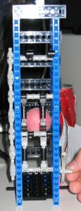
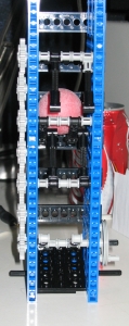
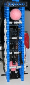
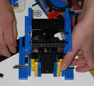
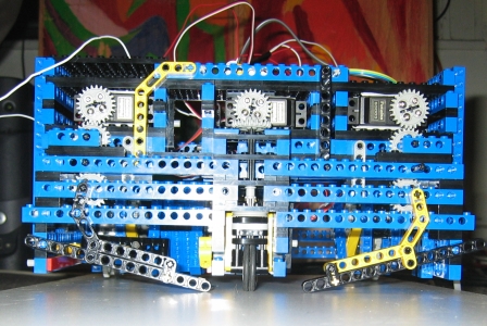
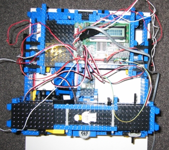
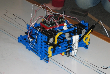
Hindenbot (Revision 3)
During the construction of our beta bot, we ran into several hurdles that we made sure to address in the construction of our new robot. Among these was the fact that we began to run out of particular parts, our dimensions exceded size specifications, and our robot was relatively slow.
The first two issues we just tried to be more conscious of during construction. However, we specifically dealt with our speed problem by reducing the gear ratios from 45:1 to 15:1, and added an extra motor to each driven wheel.
Because we had not developed a practical steering system for our beta bot, we were in unchartered territory. After debating the merits of various wheel allignments and steering strategies, we decided to servoize a single front caster to steer the robot based upon data from a gyroscope and two shaft encoders.
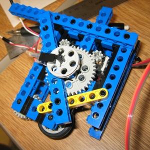
Driving in a straight line to significant amounts of time to implement. Depending on our speed, the robot would either over- or under-compensate. However, we devised a function that equally weighted data from the gyroscope with that of the shaft encoders that gave us very little error.
After developing suitable code for driving straight, we thought that it would be important to have our robot know how far it had traveled. To this end, we calculted the number of ticks in the shaft encoder per inch the robot traveled. Unfortunately, in retrospect, this implementation ignored too much of the real world: because of low coeffecients of friction, the robot would often skid (not registering any ticks on the shaft encoder).
We discussed numerous methods of solving this problem, including appending separate wheels for the shaft encoders which would turn regardless of skidding, hard coding error terms for various speeds and distances, jamming on the breaks, and decelerating as we came to a stop. After trying all of these strategies in some form or another, the only one that seemed to work was a function that discretely ramped up to a particular speed, then discretely ramped down, jammed on the breaks, coasted, and then slowly moved an additional distance until the shaft encoders read the values that corresponded to the appropriate distance. Clearly, this slowed our robot down significantly, thereby making implementation of other basic code impossible.
In addition, we developed turn code using the gyro that was fairly precise, and relied upon a quick burst of the motors, followed by small corrections.
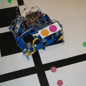
We attached 4 distinct IR sensors for initial orientation, callibrated both our balljector as well as our gates, and added 8 bump sensors.
We believe the IR sensors are primarily what did us in during the competition. Because of a slight coding error, during our orientation period, our robot chechecked the wrong sensor port, and therefore only worked correctly in 50% of its orientations.
The Competition
During seeding round 1, we scored 2 negative points for ourselves thus
qualifying for the competition.
In the second round, we scored no points, but the other team scored 3 positive
points in our scoring area.
In the competition round 1, our robot did not move at all due to the ir sensor bug. However, our servos twiched vigorously, preventing us from receiving a false start.
In the competition round 2, we were lucky enough to start in the 1 position that always avoided the ir sensor bug, quickly scored 2 points and jammed our wheels on the ridge around our scoring area for the rest of the match, thereby securing our sweet buttery victory.
In the competition round 3, we started in an orientation that would allow our
robot to work if the noise in one particular ir sensor made it vary by
over 1 point while it was waiting.
This happened halfway through the match.
Unfortunately, we backed into the other robot and were unable to score any
points for ourselves.
Our cumulative score from seeding on was +3 points. We had 1 win and 4 losses.
All of us were pleased to see our robot in action during the competition,
although we would have liked to see more of the potential we felt it could
have realized.
Regardless, we all had a lot of fun, learned a lot, and annoyed Vimal with many a blown component.