| Vital Statistics |
Photo |
| Name |
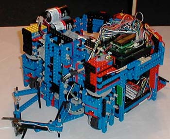
Roboteleone (Robot `eee lee `oh nee), named after our esteemed coleague, Matthew MPM Monteleone |
| Function/Strategy |
Ball Collection |
| Dimensions |
12"(W)x12"(L)x10"(H) |
| Weight Class |
Heavyweight |
| Drive Train |
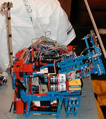
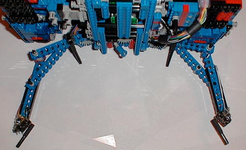
3 Wheel, Synchro-drive |
[1][2] |
| Gear Ratio |
75:1 |
| Motors per wheel |
1 |
| Other technologies incorporated |
Lifting arm, pinching claw, potentiometer-based shaft encoders, distance sensors for wall following, IR color sensing of table, remounted knob() to be used as a sensor, made menu interface buttons away from the wires surrounding the start/stop buttons |
| Lifting Arm |
Photo |
| Length |
Approx. 8" |
| Range of Motion |
240 degrees. Collected balls with arm vertical and claw facing forward (0 degrees). Loaded balls into belly at 120 degrees, claw pointing upwards. Stored arm initially up with claw pointing reverse to meet sizing specs (180 degrees) |
| Motors |
2 |
| Gear Ratio |
57:8*3:1*24:1 = 513:1 |
| Pincher Claw |
Photo |
| Size |
Open: 14"(W) x 5"(L)
Closed: 6"(W) x 6"(L) |
| Gear Ratio |
245:1 |
| Motors |
1 |
| Part Used |
Location |
Function |
Photo |
| 90% of LEGO pieces |
Everywhere |
Structure |
| 4 touch switches (3 pts.) |
2 on tips of pincher, 2 in elbows of pincher |
Ball, collision, and wall sensing |
[1] |
| 1 micro switch (0 pts.) |
Bottom of arm, approx. 1/2 diameter of ball off the ground |
Sensing success of ball-gathering after pinchers close |
[1] |
| 3 Sharp distance sensors (8 pts.) |
1 on back side of arm, pointing forward, 2/3 diameter of ball above the ground. 2 mounted 3.5" in from either side on the rear, facing out. |
Front sensor used for ball and wall detection. Side sensors used for wall following. |
[1] |
| 2 Large white switches (1 pt.) |
Rear-facing, Left-rear and Right-rear |
Rear wall detection, alignment in turning |
[1] |
| 6 50k dial-pots, modified to give full rotation ($1.20) |
Glued to wheel axle-ends, one on each side of each axle |
Shaft encoding, jam detection |
| 1 IR LED / Phototransistor pair (0 pts.) |
Shining across the opening in the belly of the robot through which balls fall |
Double checking that the ball we roll down the arm towards the opening arrives in the opening. |
| 7 IR LED / Photoresistor pairs (6 pts.) |
Underside of ball storage belly
 front
*  *  *

   *

* * * |
The 3 yellow asterisks in the diagram to the left represent the pairs used for orientation. All 7 used for line following, and other necessary color detection. |
knob()(0 pts.) |
Relocated to the roataing axle of the lifting arm. |
"Servo-ized" the dual motor-driven arm so that we could write a simple procedure to drive it to a given position. Approximately 240 degrees of motion are able to be precisely addressed.
|
| 50k dial-pot ($0.20) |
Axle on axis of rotation of last gear on pincher. |
"Servo-ized" the single motor driven pincher. Approximately 240 degrees of motion are able to be precisely addressed. |
| 6 motors (2 pts.) |
3 on wheels, 2 on lifting arm, 1 on pincher claw |
Actuate stuff |
| 3 Futaba S148 Servos ($14.00) |
1 on each of the rotating motor/gearbox legs |
Rotate the wheels straight or +-90 degrees |
| 2 green push button switches from old CD walkman ($0.40) |
Next to Handy Board |
Up/down buttons for the Handy Board menu system we wrote |
[1] |
| 1 black push button switch from old mouse ($0.20) |
Next to Handy Board |
Enter/Select button for menu system |
[1] |

 Team
Team Strategy
![[1]](images/front_left_arm_open_showing_synchrodrive.jpg)
![[2]](images/front_right_arm_open_showing_synchrodrive.jpg)
![[1]](images/right_rear_view_of_touch_and_distance_sensors.jpg)
![[1]](images/top_view.jpg)