The Robot
Drive Train (a.k.a. chassis)
The most basic and
universal part of a robot is its chassis. Almost any scoring mechanism
can be mounted to a well designed chassis.
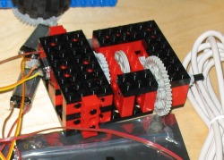
The top picture shows
our first attempt at a gear box. It is shown with only one motor in
place, but it supports up to two. Although very compact, this
gearbox was difficult to brace and mount. It also attached to
only one wheel, and the bottom of the box was too low to allow for the
smaller wheels.
Our second gearbox was easier to
brace and supported the small wheels, because not all the gears were on
the same horizontal plane. Unfortunately, it was also very bulky
and didn't take advantage of the space.
Our
third gearbox was a modification of the first one. It ended up
being the chassis we used for one of the assignments. We didn't
use this gearbox because it only supported one wheel on each side of
the robot, which would have forced us to use casters to support the
other ends of the robot.
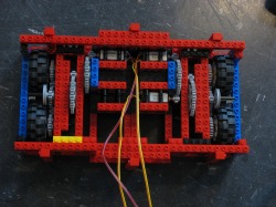
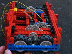
The fourth and final gearbox
incorporated all the advantages we wanted to keep from the previous
gear boxes. It supported two motors per side, while also allowing for a
base of four wheels. Its final gear ratio was 75:1 and we used the
smaller set of wheels from the kit. We had over heard in lab that a
75:1 ratio with large wheels was able to out run some of the students
in the competition, so we figured something slightly slower through the
use of smaller wheels with more torque would be a good idea.

Scoring Mechanisms
We spent a majority of our
time designing and testing our first idea for the scoring mechanism: an
arm that stretched from our blocking position in front of our
opponent's 4-pocket to our 2-pocket.
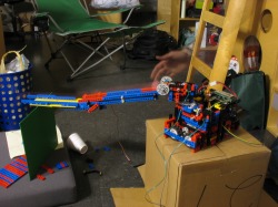
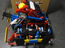
The first picture displays
the nearly complete arm. At this point we did not have a method for
depositing the balls onto the arm, but we kind of decided to ignore it
until the time came.
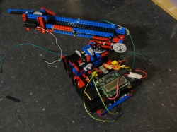
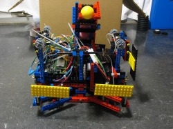
The second picture
shows more detail of the turret design, which allows the arm to unfold
from its initial position in order to meet the requirements of the
robot fitting inside the 12"x12"x12" cube.
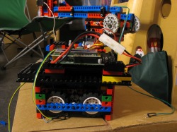
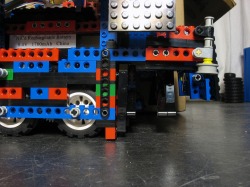
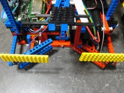
The
next picture is a view of the side of the robot. Notice the support and
bracing around the wheels of the robot. This robot also had a
specific side used for wall following, so the switches and sensors were
only needed on one side.
After the mock
competition, we decided to switch our focus to reliability.
Scrapping the arm idea, we designed a scoring mechanism that would
carry the balls in the front of the robot, then release them to the
right or left, depending which side the pocket was on. This idea
allowed for more mobility, although it required sensors on both sides
of the robot because either side would have to follow the wall.
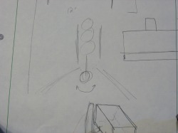
The sketch demonstrates how this new mechanism would work.
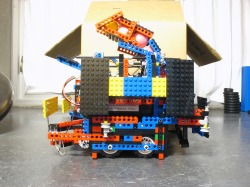
The
next two pictures show the implemented idea from different angles. The
ground level photo gives a better sense of the ramp that allows the
balls to roll into the pockets.
Here's
another picture of the robot from a more interesting angle. Notice how
we had to curve the ball chute so that it would fit in the 12" cube
size requirement.
Skunk Ball Retrieval
One of the reasons we
switched to this new idea was because almost any team could also
implement the same, simple, and effective strategy. Besides
reliability, the only other way we could distinguish ourselves from
similar robots was through the retrieval of the skunk ball.
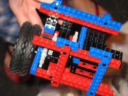
We
figured the simplest method to capture the skunk ball was to funnel it
into some sort of clamping mechanism in the center of the robot.
The
the two pictures show the general concept, with everything including
the funnel, clamping device, and IR sensor (blue brick) to detect the
skunk ball.
Navigation
In all stages of
development, our main method of navigation has been wall
following. Originally, we had switches on the sides to detect the
wall, but that turned out unreliable since the wall was not always
smooth and there was a lot of bouncing. We then decided to put
rollers on the sides of the robot and use IR sensors to detect the
pockets (as seen in picture). By setting the outside motors at a
slightly higher speed than the inner motors, we made our robot reliably
roll along the wall without any complicated mechanisms.
On the
way to the skunk ball, the robot has to turn a corner. It would
consistently get stuck in the corner and be unable to turn, so we used
the gyro to swerve out from the wall so it wouldn't be against any
walls when making the turn. On the way back from the skunk ball,
the robot uses the gyro to drive straight. This method isn't very
reliable, but since we were just aiming for some point along the front
wall, it didn't need to be.